To avoid any mishaps, the most novel solution is to use Simulation technology. These systems would mimic the real-life physical machinery, system, or application and digitally remake the scenario on the digital platform. When paired with virtual reality, the augmented reality of mixed reality, the functions of the system could be studied even better and any problem that arises in the real world can be thought to solve successfully in the digital platform. Dams compile many functions and systems that work in different sectors but have to be interconnected for the dam to function smoothly, as well as to produce electricity in the necessary demand.
What Is The Relationship Between Simulation Technology And A Water Dam?
In a water dam scenario, it is important for the management team to know every system that runs within the dam and to ensure its smooth flow. Using simulation technology, the management team could display the dam system in real-time to get a better understanding of its function, and to diagnose them with, whether or not the system requires any repairs, re-modifications, or to be disposed of. Simulation technology can also be used as a prediction tool, which means the management team could predict the status of the systems in the dam within the entered date.
The Factors That Are Subjected To Simulation Techniques And Their Applications
Hydraulic Structure
The Variable Parameters: These are used to define the scale on which the build takes place.
The Continuous Invariant Components: These are used to define the topological constraint relationship between two or more components.
Terrain Generation
Terrain Generation Based On DEM Data
A Batch process is done on a DEM base map from which the spatial point coordinates are extracted to create the terrain with the DEM data. All this depends on the data gathered from real terrain and the density of the grid points. The steps which follow in order to construct points, lines, surfaces, and entities are listed below;
- The grid points that are extracted are spread on a DEM layer.
- The grid points are connected
- The closed edges are generated and the common nodes are shared to form the terrain.
- The vertical offset of the four corners should be 0m. the surfaces that are created are enclosed to the geometric entities and the terrain is generated likewise.
Terrain Generation Based On Contour Lines
As the data obtained earlier, the grid points are placed as a point cloud, junctions are built-in to the point cloud by connecting the points. Then the enclosed lines form the landscape after which the surface is established and finally the terrain entity is generated. There are four terrain model on which the DEM and contour lines are based;
- Elevation points
- Contour lines
- Terrain surface
- Terrain entity
Conditions To Take Into Account When Generating A Simulation
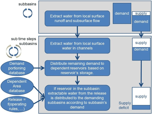
In the Initial condition; The arranged probe points diagram and the mesh of the partial computational domain. There are two conditions to the simulation, It has to be long enough to capture, the relative stability status of the downstream flow field but short enough to avoid generating many redundant data.
In the simulation period, the computational time is controlled and the water level is nearly constant, which is why the downstream flow field can achieve a relatively stable condition.
The time step is determined by the Courant-Friedrichs-Lewy (CFL) condition, which guarantees the solver of the RANS equation (Reynolds-Averaged Navier-Stokes) to receive stable solutions.


